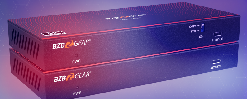
4K Ultra HD DisplayPort 1.2a KVM Extender Kit - HDBaseT, Long Range over Cat6 up to 150m, Bi-Directional POC with USB, IR & RS232
U.S.-based Company
Complimentary design services
and engineering support
and engineering support
5 year warranty
Click here to learn more
about BZBGEAR Fundamentals
Configure the Perfect Solution
Get Started
Tech Specifications
| Technical Specifications | ||||
| DP Compliance | DP 1.2a | |||
| HDCP Compliance | HDCP 2.2 | |||
| Video Bandwidth | Up to 21.6Gbps | |||
| Video Resolution | Up to 4K@60Hz YUV 4:4:4 | |||
| USB Compliance | USB 1.1 | |||
| HDR | HDR, HDR10, HDR10+, Dolby Vision, HLG | |||
| Color Space | RGB, YCbCr 4:4:4 / 4:2:2, YCbCr 4:2:0 | |||
| Color Depth | 8/10/12-bit | |||
| Audio Formats | LPCM 2.0 (96KHz), Dolby Digital Plus 5.1CH and DTS-HD Master 7.1CH |
|||
| IR Level | 5Vp-p/12Vp-p | |||
| IR Bandwidth | 20K - 60KHz | |||
| Transmission Distance | 1080P@60Hz - 492ft /150m, 4K@60Hz - 328ft /100m | |||
| ESD Protection | Human body model: ±8kV (Air-gap discharge) & ±4kV (Contact discharge) | |||
| Connections | ||||
| Transmitter | Input: 1 x DP IN [20-pin female] Output:1 x HDBT OUT [RJ45, 8-pin female] Control: 1 x IR IN [3.5mm Stereo Mini-jack] 1 x IR OUT [3.5mm Stereo Mini-jack] 1 x RS-232 [3 pin-3.81mm Phoenix jack] 1 x PC [USB-A] 1 x Service [Micro USB] |
|||
| Receiver | Input: 1 x HDBT IN [RJ45, 8-pin female] Output: 1 x DP OUT [20-pin female] Control: 1 x IR IN [3.5mm Stereo Mini-jack] 1 x IR OUT [3.5mm Stereo Mini-jack] 1 x RS-232 [3 pin-3.81mm Phoenix jack] 2 x USB 1.1 [USB-A] 1 x Service [Micro-USB] |
|||
| Mechanical | ||||
| Housing | Enclosure - Metal Composite | |||
| Color | Black | |||
| Dimensions (L x W x H) | 5.5in x 2.6in x 0.71in [140mm x 65mm x 18mm] | |||
| Weight | 0.5 lbs (8oz) [0.45kg] | |||
| Power Supply | DC 24V/1A (US/EU standard, CE/FCC/UL certified), Bi-directional POC | |||
| Power Consumption | Total power consumption: 13.2w | |||
| Operating Temperature | 32° - 104°F / 0° - 40°C | |||
| Storage Temperature | -4° - 140°F / -20° - 60°C | |||
| Relative Humidity | 20 - 90% RH (no condensation) | |||
| Resolution | 8K30 | 4K60 | 4K24 | 1080P60 |
| Cable Length | 9.8ft / 3m | 16ft / 5m | 32ft / 10m | 66ft / 20m |
| NOTE: The use of “Premium High Speed” HDMI 2.1 cables is highly recommended. | ||||
Resources
Documents
PACKAGE CONTENTS
- 1x BG-EXD-150C Transmitter
- 1x BG-EXD-150C Receiver
- 1x 24V / 1A Locking Power Supply
- 1x IR Blaster Cable (1.5m)
- 1x IR Receiver Cable (1.5m)
- 2x 3-pin 3.81mm phoenix connectors
- 4x Mounting ears
- 8x KM3*4 Machine Screws
- 1x 1.5m USB 2.0 Cable (A to B)
- 1x User Manual
Interfaces

- PWR LED: The red LED is on when the Transmitter is powered on.
- EDID DIP switch: Used for EDID setting (COPY by default).
COPY: Copy the EDID of the DP OUT port of Receiver.
STD: Default 1080P 2CH. - SERVICE: Micro USB port, used to update MCU firmware.
- DC 24V: DC 24V/1A power input port.
Note: The extender supports POC functionality which means
that either Transmitter or Receiver is connected to 24V/1A
power supply, the other does not need a power supply. - HDBT OUT: HDBT output port, connected to the HDBT IN port of the Receiver with CAT6 cable.
- Link Signal Indicator (Green): Solid: Transmitter and Receiver are in good connection status.
Flashing: Transmitter and Receiver are in poor connection status.
Dark: Transmitter and Receiver are not connected. - Data Signal Indicator (Yellow): Solid: DP signal with HDCP.
Flashing: DP signal without HDCP.
Dark: No DP signal. - DP IN: DP signal input port, connected to DP source device such as computer host.
- IR IN: Connected to IR receiver cable. The IR receive signal will emit to the IR OUT port of the Receiver.
- IR OUT: Connected to IR blaster cable. The IR emit signal is from the IR IN port of the Receiver.
- RS-232: 3-pin phoenix connector, connected to a PC or control system for RS-232 command transmission.
- PC: USB-B port, connected to PC.
- PWR LED: The power LED is on when the Receiver is powered on.
- SERVICE: Micro USB port, used to update MCU firmware.
- DC 24V: DC 24V/1A power input port.
Note: The extender supports POC functionality which means
that either Transmitter or Receiver is connected to 24V/1A
power supply, the other does not need a power supply. - HDBT IN: HDBT input port, connected to the HDBT OUT port of the Transmitter with CAT6 cable.
- Link Signal Indicator (Green): Solid: Transmitter and Receiver are in good connection status.
Flashing: Transmitter and Receiver are in poor connection status.
Dark: Transmitter and Receiver are not connected. - Data Signal Indicator (Yellow): Solid: DP signal with HDCP.
Flashing: DP signal without HDCP.
Dark: No DP signal. - DP OUT: DP signal output port, connected to DP display device such as TV or monitor.
- IR IN: Connected to the IR receiver cable. The IR receive signal will emit to the IR OUT port of the Transmitter.
- IR OUT: Connected to the IR blaster cable. The IR emit signal is from the IR IN port of the Transmitter.
- RS-232: 3-pin phoenix connector, connected to a PC or control system for RS-232 command transmission.
- USB-A: Two USB-A ports, connected to a keyboard or mouse.


